5SHX2645L0004 IGBT 的开关特性是指漏极电流与漏源电压之间的关系。IGBT 处于导通态时,由于它的PNP 晶体管为宽基区晶体管,所以其B 值极低。尽管等效电路为达林顿结构,但流过MOSFET 的电流成为IGBT 总电流的主要部分。此时,通态电压Uds(on) 可用下式表示Uds(on) = Uj1 + Udr + IdRoh式中Uj1 —— JI 结的正向电压,其值为0.7 ~1V ;Udr ——扩展电阻Rdr 上的压降;Roh ——沟道电阻。通态电流Ids 可用下式表示:Ids=(1+Bpnp)Imos5SHX2645L0004式中Imos ——流过MOSFET 的电流。5SHX2645L0004由于N+ 区存在电导调制效应,所以IGBT 的通态压降小,耐压1000V的IGBT 通态压降为2 ~ 3V 。IGBT 处于断态时,只有很小的泄漏电流存在。5SHX2645L0004 IGBT 在开通过程中,大部分时间是作为MOSFET 来运行的,只是在漏源电压Uds 下降过程后期, PNP 晶体管由放大区至饱和,又增加了一段延迟时间。td(on) 为开通延迟时间,tri 为电流上升时间。
5SHX2645L0004
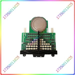
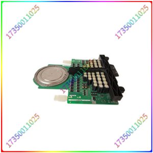
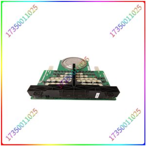
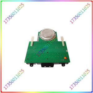
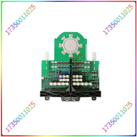
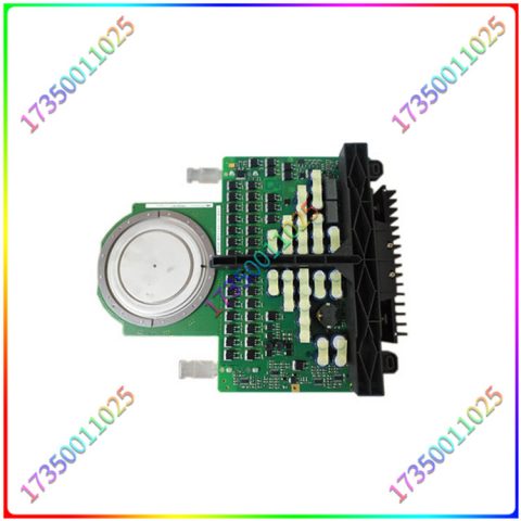
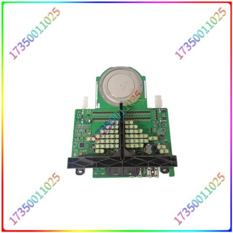
5SHX2645L0004 ABB IGCT具有电流大、阻断电压高、开关频率高、可靠性高、结构紧凑、低导通损耗等特点,而且制造成本低,成品率高,有很好的应用前景。通常在器件设计中,如果需要高的阻断电压值,就得要求硅片的厚度增加。但硅片厚度的增加必将导致导通和开关损耗的增大。IGCT采用缓冲层结构后,在相同阻断电压下,硅片厚度和标准结构更薄,从而大大降低了导通和开关损耗,从而提高了器件的效率。采用缓冲层还使单片GCT与二极管的组合成为可能。5SHX2645L0004 ABB IGCT驱动中最具特点的是其借助集成门极电路实现的“门极换流”和“硬驱动”关断过程。
5SHX2645L0004
实际应用中常给出的漏极电流开通时间ton 即为td (on) tri 之和,漏源电压的下降时间由tfe1 和tfe2 组成。IGBT的触发和关断要求给其栅极和基极之间加上正向电压和负向电压,栅极电压可由不同的驱动电路产生。当选择这些驱动电路时,必须基于以下的参数来进行:器件关断偏置的要求、栅极电荷的要求、耐固性要求和电源的情况。因为IGBT栅极- 发射极阻抗大,故可使用MOSFET驱动技术进行触发,不过由于IGBT的输入电容较MOSFET为大,故IGBT的关断偏压应该比许多MOSFET驱动电路提供的偏压更高。
5SHX2645L0004
The switching characteristics of 5SHX2645L0004 IGBT refer to the relationship between drain current and drain source voltage. When IGBT is in the on state, its B value is extremely low due to its PNP transistor being a wide base transistor. Although the equivalent circuit is a Darlington structure, the current flowing through the MOSFET becomes the main part of the total current of the IGBT. At this point, the on state voltage Uds (on) can be represented by the following equation: Uds (on)=Uj1+Udr+IdRoh. In the equation, Uj1- the forward voltage of the JI junction, which is 0.7-1V; Udr – voltage drop on the extended resistor Rdr; Roh – channel resistance. The on state current Ids can be represented by the following equation: Ids=(1+Bpnp) Imos5SHX2645L0004, where Imos – the current flowing through the MOSFET. Due to the conductivity modulation effect in the N+region of 5SHX2645L0004, the on state voltage drop of IGBT is small, and the on state voltage drop of IGBT with a withstand voltage of 1000V is 2-3 V. When IGBT is in the off state, only a small leakage current exists. During the turn-on process of the 5SHX2645L0004 IGBT, most of the time it operates as a MOSFET. However, in the later stage of the drop in drain source voltage Uds, the PNP transistor increases its delay time from amplification to saturation. Td (on) is the opening delay time, and tri is the current rise time.
5SHX2645L0004
5SHX2645L0004 ABB IGCT has the characteristics of high current, high blocking voltage, high switching frequency, high reliability, compact structure, low conduction loss, and low manufacturing cost, high yield, and has good application prospects. Usually, in device design, if a high blocking voltage value is required, an increase in the thickness of the silicon wafer is required. However, an increase in the thickness of silicon wafers will inevitably lead to an increase in conduction and switching losses. After adopting a buffer layer structure in IGCT, the silicon wafer thickness and standard structure are thinner under the same blocking voltage, greatly reducing conduction and switching losses, thereby improving the efficiency of the device. The use of buffer layers also makes it possible to combine single chip GCTs with diodes. The most distinctive feature of the 5SHX2645L0004 ABB IGCT driver is its use of integrated gate circuits to achieve “gate commutation” and “hard drive” shutdown processes.
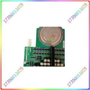
5SHX2645L0004
The opening time ton of the drain current commonly given in practical applications is the sum of td (on) tri, and the decrease time of the drain source voltage is composed of tfe1 and tfe2. The triggering and turning off of IGBT requires applying positive and negative voltages between its gate and base, and the gate voltage can be generated by different driving circuits. When selecting these driving circuits, it is necessary to based on the following parameters: device off bias requirements, gate charge requirements, resistance requirements, and power supply conditions. Due to the high gate emitter impedance of IGBT, MOSFET driving technology can be used for triggering. However, due to the larger input capacitance of IGBT compared to MOSFET, the turn-off bias of IGBT should be higher than the bias provided by many MOSFET driving circuits.



There are no reviews yet.